Accelerating and braking
What happens when we step on the gas or brake in a car? The car pushes against the road to either accelerate (gas pedal) or decelerate (brake pedal). But how are the forces on the car and wheels distributed? What determines whether the wheels grip the road or lose traction and spin or slide?
To study this problem we need a model. Let's start with the simplest model and then gradually consider more complex models.
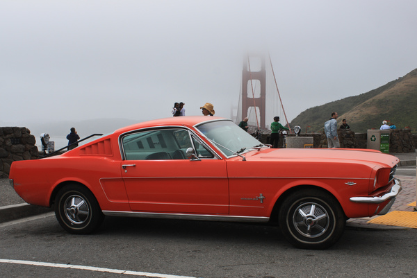
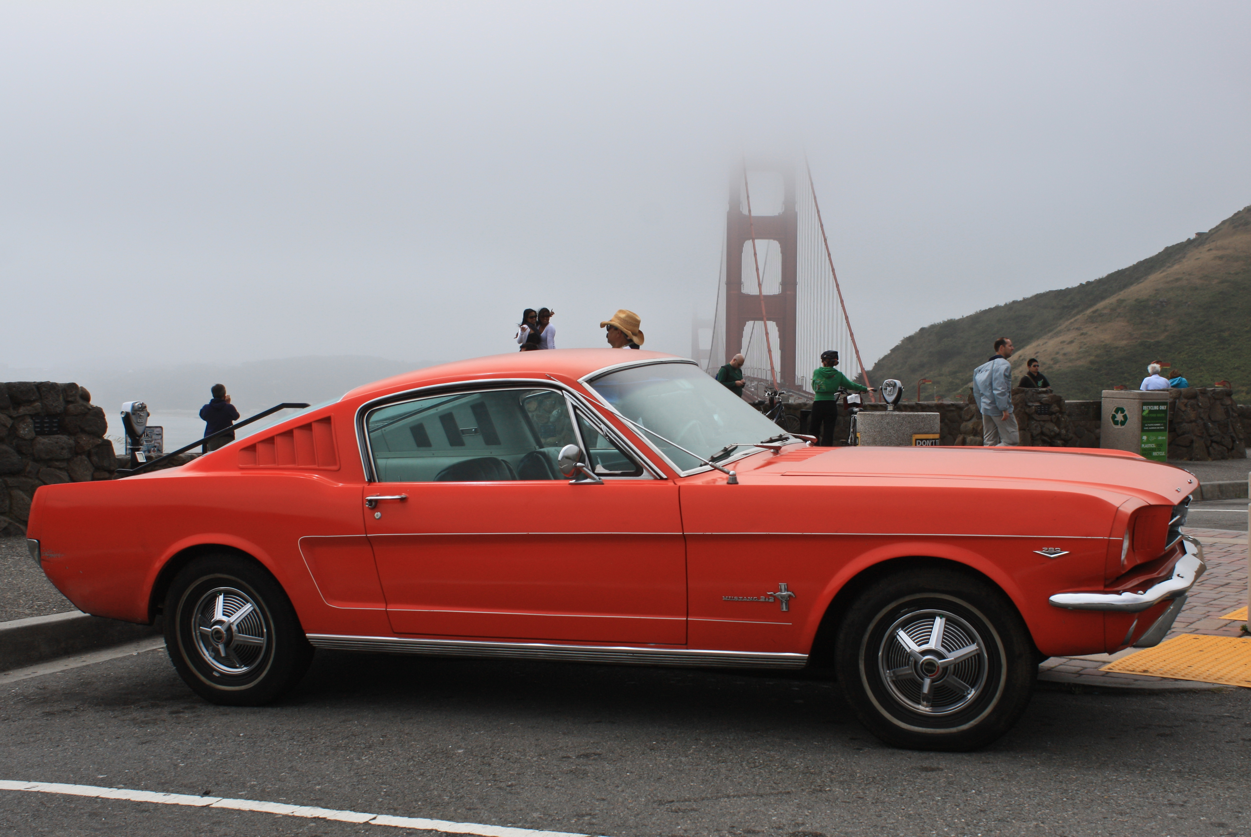
The classic American Pony Car: a 1965 Ford Mustang Fastback with the Golden Gate Bridge in the background. Image source: flikr image by Nick Ares (CC BY-SA 2.0) (full-sized image).
- Video of a burnout with a deliberate loss of traction.
- Video of a wheelie, where the front wheels lose contact.
- Video of braking in which the rear wheels lose contact.
- Another burnout video, taken to the point of destruction.
Point mass model
The simplest model of a car is to treat the entire vehicle as a point mass. On a we have vertical force balance for a stationary car. When the car , there is a horizontal forward force on the car, and a corresponding backwards horizontal force on the ground. As the car picks up speed, air resistance produces a backwards force. On the diagram we have drawn some forces offset from the center of mass, so that the vectors don't overlap. Because we are assuming a point mass model, however, all vectors are really acting at the same point.
While cruising at a constant speed, there is a balance between the horizontal driving force and the drag force due to air resistance. When the car , there is a backwards force that slows the car down to a stop.
We can think of the force vectors (such as the ground force on the car) as either in separate horizontal and vertical or as unified vectors. It may be helpful to pause the during and to consider the forces at work.
2D rigid body model
Consider a car sitting stationary on the ground, as shown below. We will take the entire car plus wheels to be a single rigid body. Clearly this is inaccurate (the wheels can't turn), but it is still useful.
We start with the car stationary, sitting on the road. Gravity acts downward through the center of mass, while there are upwards reaction forces on the wheels and corresponding equal and opposite forces downwards on the ground. Because the car is not accelerating, the total forces on the car are in balance, as we can see on the .
When the driver , this results in the car pushing back on the road, giving a net forward force on the driving wheels (the back wheels for our car), and the car accelerates up to cruising speed. Here we are including air resistance but neglecting rolling resistance, and while cruising at constant speed the driving force exactly balances the drag force from air resistance. When the driver , the car pushes on the road to slow down, giving backward forces on both wheels and causing the car to decelerate to a stop.
Repeat the / cycle a few times while showing the . Observe the horizontal and vertical forces of the road on the car wheels. Also view the forces both in and as total force vectors.
The vertical forces of the road on the car always need to balance the gravitational force, but we can see that the distribution between front and rear wheels changes as the car accelerates and decelerates. This is because the horizontal driving and braking forces are below the center of mass and produce a moment. The vehicle is not rotating, so this moment must be counteracted by the ground forces. The force directions mean that the rear wheels take more weight during acceleration, while the front wheels take more weight during braking.
Traction, acceleration, and braking
The maximum force with which the car can push against the road is limited by the friction coefficient of the tire multiplied by the normal force. This applies both during acceleration and braking.
To accelerate as hard as possible, we should thus use a rear-wheel drive layout. If we accelerate too hard, however, then the back wheels will slip and experience wheelspin, because the dynamic coefficient of friction is lower than the static coefficient. While high-performance applications generally want to maintain traction in all cases, the impressive effects of traction loss are sometimes deliberately produced. Spinning the rear wheels in a burnout produces smoke as the tires vaporize due to the heat from friction. Drag racers perform a burnout at the start of a race to clean the tires and heat them to an optimal temperature. To easily produce a burnout a line lock can be installed to enable the brakes to be applied only to the front wheels (although this is often illegal on street cars). Alternatively, a burnout can be performed by disengaging the clutch, running the engine at a high revs, and then rapidly engaging the clutch. The high angular momentum of the engine then provides a rotational impulse to the rear wheels, causing them to lose traction.
Even if traction is maintained during acceleration, a second problem that may occur is that the torque from the rear wheels can be enough to lift the front wheels off the ground, so that the vehicle performs a wheelie. This occurs very easily for motorbikes and BMX bicycles, due to a high center of mass to wheelbase ratio, but can also occur for cars with poor geometry and sufficient power.
The problems of wheel slip and wheel lift-off occur in reverse while braking. Any car with well-maintained brakes has sufficient braking power to cause the wheels to lock, even in dry conditions with good traction. For this reason many cars now include anti-lock braking systems (ABS), which detect wheel locking and rapidly pulse the brake force to prevent locking. Even better than this are electronic brakeforce distribution (EBD) systems, which apply the maximal brake force to each wheel while maintaining traction and control, better than any unassisted human driver could achieve. Due to the weight transfer to the front wheels during braking, the front brakes generally apply much greater force and thus wear out sooner than the rear brakes.
Using ABS to mean Anti-lock Brake System is an example of a backronym. This is where the name ABS came first, and then Anti-lock Brake System was made up later to fit the letters as an ackronym. In fact ABS comes from the German phrase Antiblockiersystem (literally: Anti Locking System).
2D multi-body model
To understand how forces and moments act on the wheels, we need to separate out the single rigid-body model into multiple rigid bodies. The simplest version of this has one rigid body for the body, and four rigid bodies for the wheels. We will assume that the two front wheels always act as a pair (same forces, same motion), and similarly for the two back wheels.
Again we start with the car stationary, and on the we see the balance of vertical forces. Remember that the force shown on each wheel is really doubled, as there are two front and two rear wheels.
If we now , then we see a clockwise moment applied to the rear (driving) wheels. This causes the wheel to rotate, but friction forces means that it must roll without slipping, so there must be a forward contact force causing it to accelerate forwards. Counteracting this is a backwards reaction force from the car on the wheel. On the car we see that there are equal and opposite forces and moments at the axles. Just as in the single rigid body case, we have a net horizontal force causing forward acceleration, and moment balance means that the weight of the car is transferred primarily to the rear wheels.
applies backwards moments to both wheels, causing them to slow down. To maintain non-slip, there is a backwards force from the ground at the point of contact. Because the wheel is slowing down, the car pushes forward on the axle. The ground/axle forces are trying to rotate the wheel forward, which must be counteracted by the braking moment. The braking moment is thus counteracting both the rotational inertia of the wheel, as well as the force couple from the ground/axle forces. Of these, the force couple is much larger (stopping a wheel without the car attached would be comparatively easy for the brakes). During braking we see again the weight being transferred to the front wheels.
More complex models
While we can learn a lot about car performance from the simple rigid body and multi-body models, there is a great deal of physics neglected by these models, which can be important for engineering design.
Both the car and the tires are deformable bodies. The deformation of the tire is responsible for the contact patch which generates the friction forces that allow a car to accelerate and brake. The physics of the frictional contact between the tire and ground can be very complex, as can the geometry of the tire. Modern tires have complex tread patterns with grooves and lugs that are designed to channel away water and snow, maintaining traction even in challenging conditions.
As well as being individually deformable, the wheels are are not rigidly connected to the car body as above, but they are actually connected by a suspension system, consisting of linkages, springs, and shock absorbers. These enable both a comfortable ride and safe handling of the vehicle.
The simple models above included a simple model of air resistance, but they neglected rolling resistance. This is the force primarily produced by the tire being compressed and re-expanded at the contact with the ground as it rolls, producing a backward force on the wheel. Using steel wheels on steel can result in trains having up to ten times lower coefficients of rolling resistance than car tires, which is one reason for the efficiency of rail transport.
There is evidence that the wrinkling of fingers in water may serve the same purpose as tread patters on tires, improving traction in wet conditions by forming channels to carry away water. This hypothesis is supported by the fact that finger wrinkling relies on an active nervous system response, meaning that the fingers of corpses cannot wrinkle (but what about zombies' fingers?).
Brake system design
The above model shows equal brake force applied on the front and rear wheels. This both inefficient and dangerous, as the rear wheels will lock while the front wheels are still turning. See #avs for steering and sliding. We want to apply more force on the front brakes, so that we can deliver the most total force while still having no sliding. This can be achieved by electronic brakeforce distribution (EBD) systems, however traditional systems are also possible.
The basic outline of a brake system is that the brake pedal pushes on a master cylinder, which compresses hydraulic brake fluid in the brake lines. This then pushes on slave cylinders in each wheel, which push the brake pads onto the brake rotors (for disc brakes; drum brakes are somewhat different). The combination of slave cylinders and brake pads and their housing is called a brake caliper.
To apply more force to the front brakes, one simple system used in practice is to have the front-wheel slave cylinders have a larger diameter than those on the rear wheels. Because the pressure in the brake lines is the same everywhere, the force exerted by the pistons is proportional to their cross-sectional area, resulting in more force with the larger-diameter front-wheel cylinders.
Modern cars use more advanced systems. The master cylinder typically contains two pistons in a parallel arrangement, so that it can apply pressure to the front or rear brake lines even if the other brake line develops a leak. A metering valve applies pressure to the rear brakes before the front, improving vehicle steering stability and allowing mixed drum/disc systems to be used. A pressure differential valve detects brake hydraulic leaks by sensing different front/rear line pressures. A proportioning valve assists with applying a different pressure distribution to the rear brakes.
Car model
This is a 1965 Ford Mustang Fastback. The mass of the car body is 1100 kg and each of the wheels has mass 20 kg, giving a total mass of 1180 kg. We assume that the wheels are uniform cylinders. The dimensions of the car are shown below.
|
\[\begin{aligned} h_1 &= {0.31\rm\ m} & \ell_1 &= {0.98\rm\ m} \\ h_2 &= {0.29\rm\ m} & \ell_2 &= {1.41\rm\ m} \\ h_3 &= {0.79\rm\ m} & \ell_3 &= {1.41\rm\ m} \\ & & \ell_4 &= {0.80\rm\ m} \end{aligned}\] |
The force of air resistance was computed above using the quadratic drag equation which is a good approximation for medium- to high-velocity motion in air:
\[F_{\rm D} = \frac{1}{2} \rho v^2 C_{\rm D} A\]
Here \(F_{\rm D}\) is the drag force, \(\rho = 1.23\rm\ kg/m^3\) is the air density, \(v\) is the velocity, \(C_{\rm D}\) is the drag coefficient (taken to be 0.3 for the Mustang), and \(A\) is the reference area (approximately the cross-sectional area, taken to be \(2.2\rm\ m^2\) for the Mustang).